

Two-Color Injection Molding Process

Author:SWITEK
|
Release Date:2026.08.25
|
Views:802

180.gif


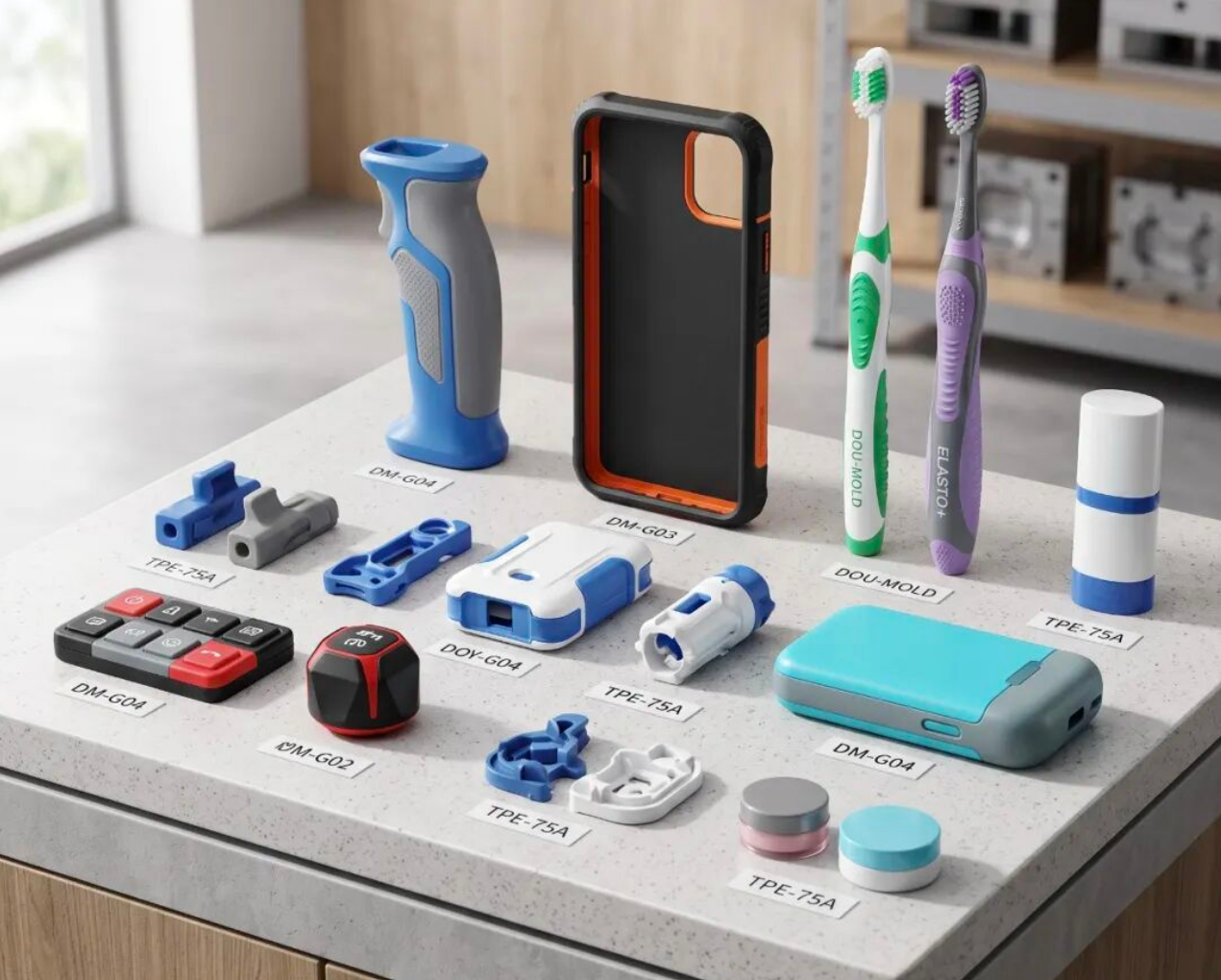
Two-color injection molding also belongs to the broad category of multi-component injection molding, and in many industries it is also commonly referred to as stack injection molding. The process logic is: first injection mold a rigid hard substrate, then overlay an elastic material on the surface layer of the substrate — most commonly polyurethane elastomer. Two different materials/colors of plastic complete permanent bonding and fusion within the mold.

The final product not only presents a two-color effect in appearance, but its internal and external structures also possess differentiated mechanical properties. The hard substrate ensures overall structural strength, while the outer soft layer provides anti-slip, shock-absorbing, and impact-resistant characteristics. The two materials are firmly combined into a single whole, eliminating the need for post-glue bonding and assembly.
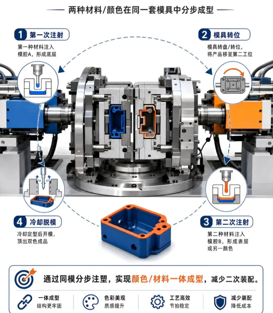
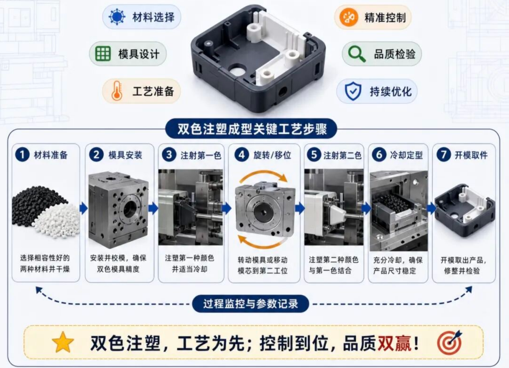
Two-color injection molding schematic
01

Two-Color Injection Molding ≠ Post-Secondary Overmolding

Secondary overmolding means the hard part is first made separately, then manually placed into another mold to inject the soft material, relying on physical wrapping and positioning for fixation — with large gaps and a tendency to come unglued.

Two-color injection molding uses same-mold rotary table molding throughout the entire process, where the interface of the two materials fuses into a whole with extremely small gaps. Its structural stability is unmatched by the overmolding process.

I. First Shot: Hard Substrate

After the machine closes the mold, the left barrel first injects the main material into the first set of cavities, creating the hard rubber base of the product — that is, the semi-finished substrate. The left and right stations work simultaneously: while the left side is injecting the first substrate, the right station is simultaneously injecting the outer layer material onto the semi-finished product from the previous round. The two barrels discharge material simultaneously, so the injection molding machine must be equipped with two independent nozzles — one for the substrate material and one for the outer cladding material.

II. Mold Opening and 180° Rotary Indexing

After the substrate cools and sets, the mold opens. The entire set of moving mold cores carrying the semi-finished products rotates half a turn along with the injection molding machine's rotary table. The hard rubber semi-finished product just made on the left side transfers to the right second fixed mold station; meanwhile, the empty core on the other side rotates to the left, ready to inject the next new substrate.

III. Second Shot: Cladding Injection

After the rotary table rotates into position, the mold closes again. The second nozzle ejects the second color/soft rubber raw material, wrapping it around the outside of the hard substrate to form the surface layer. During this process, the left side continues to inject new substrates while the right side clads finished products — both processes run in parallel with no idle waiting time.

IV. Final Demolding and Part Ejection

The mold opens again, and the finished product that has completed two injection shots remains on the moving mold. The ejector pins directly push out the complete two-color part for discharge.

02

Basic Working Principle of Two-Color Injection Molding

The two-color/dual-material injection molding process works by stepwise injecting the first material into cavity A to form the base layer in the same mold, rotating the mold rotary table to the second station, then injecting the second material to form the surface layer, and finally cooling, opening the mold, and ejecting the finished product. Its core advantage lies in achieving integrated molding of color and material, thereby significantly reducing secondary assembly, improving structural firmness, production efficiency, and appearance quality, while effectively lowering production costs.

Working principle diagram 1        Working principle diagram 2
03

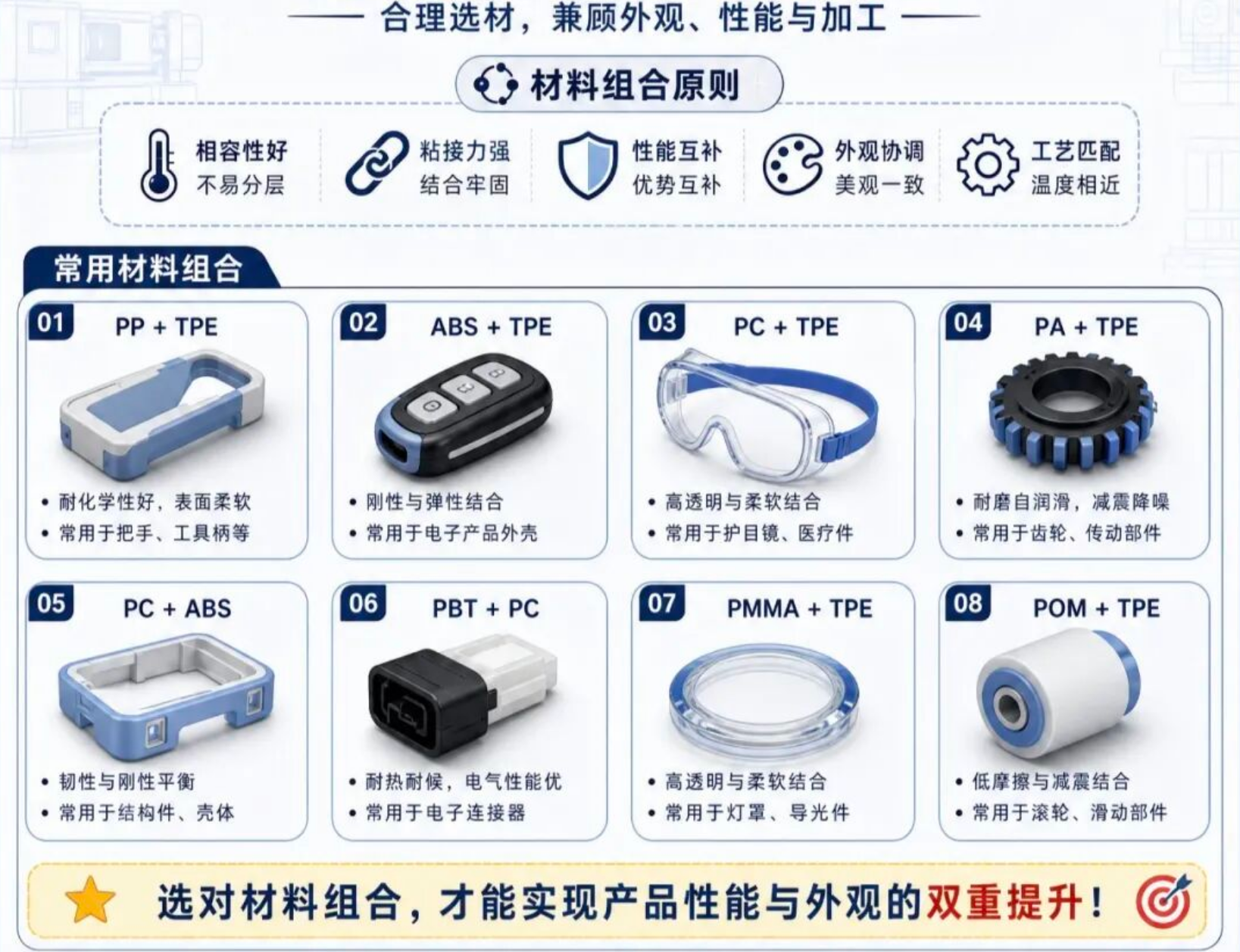
Common Two-Color Injection Molding Material Combinations

Select substrate and cladding materials with good compatibility:

Common two-color injection molding material combination table
04

Common Defects in Two-Color Injection Molding

The above 15 two-color injection molding defects are reorganized and integrated into paragraph-style explanations across three core dimensions: appearance & molding, structure & demolding, and two-color process-specific:

I. Appearance Defects (Surface Finish, Color, and Surface Blemishes)

Surface Marks and Discoloration (Black Specks, Silver Streaks, Flow Marks, Burning): Mainly originating from raw material contamination, residual moisture, or overheating decomposition. Raw materials mixed with impurities or prolonged high-temperature residence in the barrel tend to form black specks; undried moisture and volatiles in the raw material or flow-entrained air easily produce silver streaks; low melt flow speed or excessively low mold temperature tends to cause flow marks; while poor venting, excessively fast injection speed, or overly high material temperature causes gas to be compressed and locally burned. Controlling dust filtration, fully drying raw materials, optimizing mold temperature and venting, and appropriately reducing material temperature and speed can effectively improve these issues.

Uneven Appearance Color (Color Difference, Light Leakage): Color differences are mostly caused by different raw material batches, uneven color masterbatch dispersion, and material temperature fluctuations, which need to be resolved by unifying batches, enhancing mixing, and fixing process parameters; light leakage mostly occurs on light-transmitting or light-shielding parts, mainly caused by uneven shell wall thickness, uneven distribution of light-transmitting materials, or excessive two-color fit gaps, requiring optimization of wall thickness design and improvement of mold precision to enhance sealing.

II. Structural and Physical Defects (Dimension, Filling, and Demolding)

Filling and Molding Dimension Defects (Flash/Burrs, Short Shots, Weld Lines): Insufficient clamping force, excessively high holding pressure, or worn clamping surfaces cause rubber material to overflow and form flash (requires increasing clamping force and repairing the parting surface); conversely, insufficient injection volume or pressure, or undersized runners, leads to short shots (requires increasing injection volume and pressure). When the temperature at the confluence of two melt streams is low, filling is slow, or venting is poor, obvious weld lines will appear, which need to be eliminated by increasing material and mold temperatures, raising injection speed, and enhancing venting.

Demolding and Internal Stress Damage (Ejector Marks, Cracking, White Edges): Ejector marks are mainly caused by excessive ejection force, insufficient draft angle, or rough mold walls, requiring polishing of mold surfaces, increasing draft angles, and reducing ejection speed; cracking originates from poor material toughness or excessive injection pressure leading to internal stress concentration, and high-toughness materials should be selected and holding pressure and cooling optimized; white edges are commonly seen at overmolding edge overflow or poor mold clamping, requiring inspection of mold wear, adjustment of fit dimensions, and reduction of holding pressure.

III. Two-Color/Multi-Material Process-Specific Defects (Bonding and Compatibility)

Poor Bonding Between Two Materials (Delamination, Color Bleeding): Delamination is usually caused by poor compatibility between the two materials, low melting temperature, or insufficient back pressure shearing, resulting in the interface being unable to bond firmly — material matching must be confirmed and melting temperature and back pressure increased; color bleeding is caused by excessive viscosity difference between the two materials or overly fast injection speed leading to unstable flow front, which in turn disrupts the boundary line — material ratios need to be readjusted and injection speed and material temperature optimized to ensure a smooth transition at the interface.


Article Source: Injection Molding Memo

Disclaimer: The content and images contained herein are sourced from public channels such as the Internet and WeChat official accounts. We maintain a neutral stance toward the viewpoints expressed in this article, which is for reference and exchange only. The copyright of republished articles belongs to the original authors and institutions. If there is any infringement, please contact us for removal.


Likes
Communicate
Share
×
Contact Us
Contact QR Code
Scan WhatsApp QR to Contact Us
    • Stock Code
      838363
    • +86 186 6517 1961

      +86 186 6687 8722

About
Products & Solutions
News
Contact
Stock Code
838363

Hotline

+86 186 6517 1961
Chat

WhatsAPP

+86 18665171961

Top